Phase Doppler Interferometry Theory |
|
|
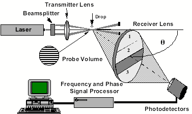
Click Here for an animated explanation of the Phase Doppler Interferometry system (requires Adobe ShockWave plug-in). In the basic PDI optical system, a laser beam is split into two beams of equal intensity. The beams are then focused and made to intersect using a transmitter lens. Individual droplets passing through the beam intersection region (probe volume) will scatter light that is collected by the optical receiver consisting of a lens and three photodetectors. The preferred light collection position for the receiver is at an off-axis angle of from 25 to 45 degrees to the transmitted beam direction measured from a plane passing through the two intersecting beams. The optical axis of the receiver should be in a plane that passes through the intersection of the beams, and is orthogonal to the plane formed by the two intersecting beams.
Schematic of the basic Phase Doppler Interferometer (PDI) system.
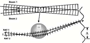
Simple diagram showing the light rays and waves incident on a spherical particle and the phase Since the rays from each beam enter the droplet at different angles, they must pass on different paths to reach a common point P. The sphere has an index of refraction, m, that is different than the surroundings. Thus, the difference in the optical path length of ray 1 from beam 1 relative to ray 2 from beam 2 will produce a phase shift between light waves traveling in the directions shown by ray 1 and ray 2 to the point P. An interference fringe pattern will form in the distant space surrounding the drop. Under ideal conditions, the interference fringe pattern will have a sinusoidal intensity distribution and will form a hyperbolic set of curves when projected onto a plane. The wavelength of the pattern at a given location will be inversely proportional to the drop diameter. This phase shift can be calculated easily and exactly using the geometrical optics theory. Given a specific location in space (points on the receiver lens aperture) the phase shift between the light scattered from each beam will vary in proportion to the drop diameter.
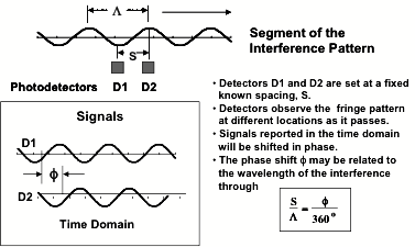
Scheme used for rapidly measuring the spacing, L of the interference fringes produced by the scattered light. Measurement of the spacing of the interference fringes produced by the scattered light is accomplished in a straightforward manner using pairs of detectors. For this approach, pairs of detectors are located in the fringe pattern, or an image of it, and the separation S between the detectors is known. When the particle or drop is moving, the usual Doppler shift in the frequency of the scattered light occurs. The difference in the Doppler frequency shift between the light scattered from beam 1 and beam 2 causes the fringe pattern to appear to move. As the pattern sweeps past the detectors at the Doppler difference frequency, each detector produces a signal that is similar in frequency but shifted in phase. The frequency and phase are measured by a dedicated signal processor and used to calculate the velocity and size of the moving droplet. |